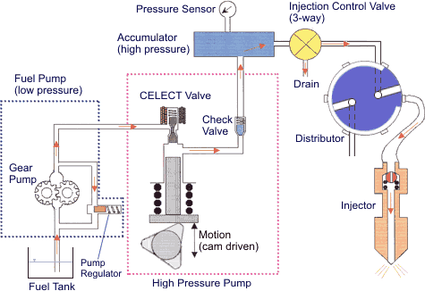
Cummins M11 Fuel System Diagram
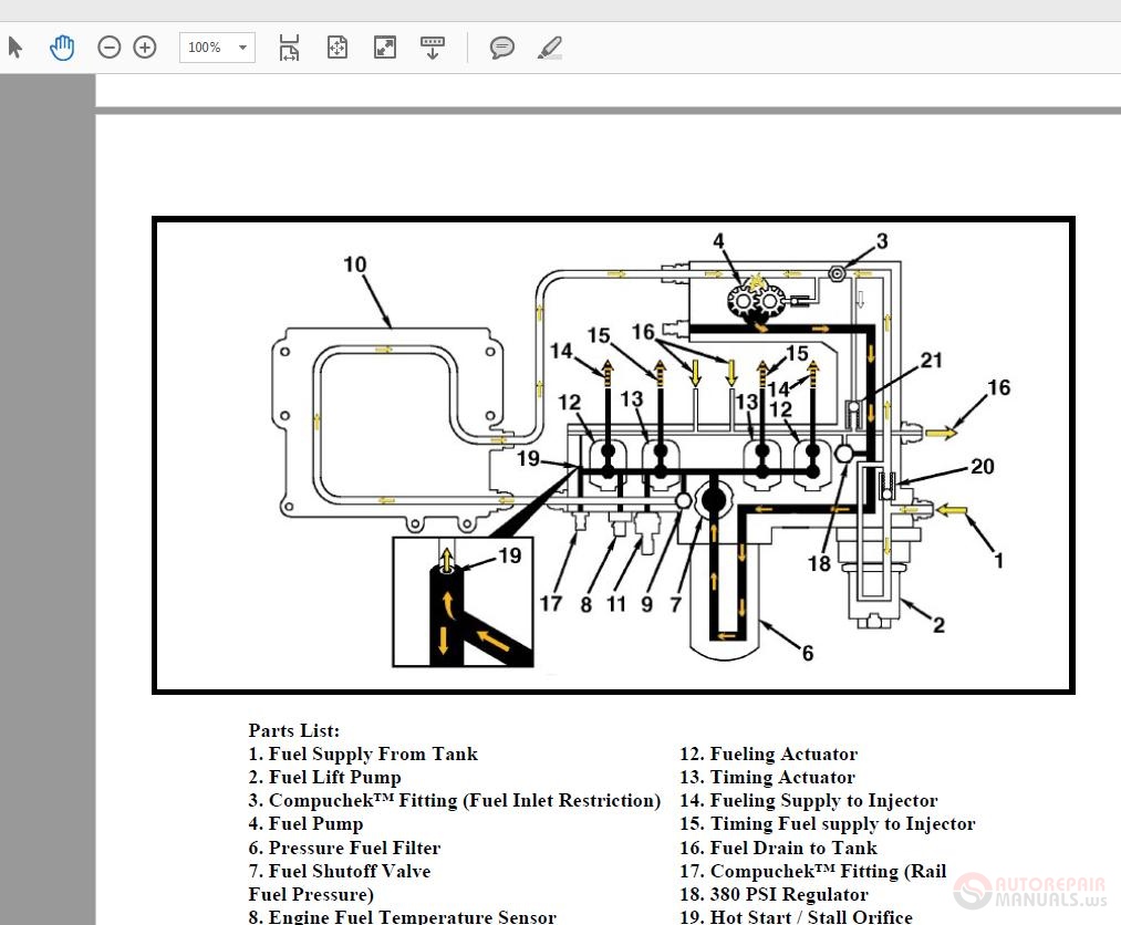
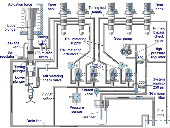
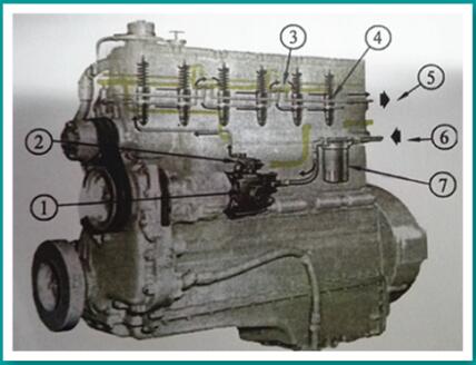
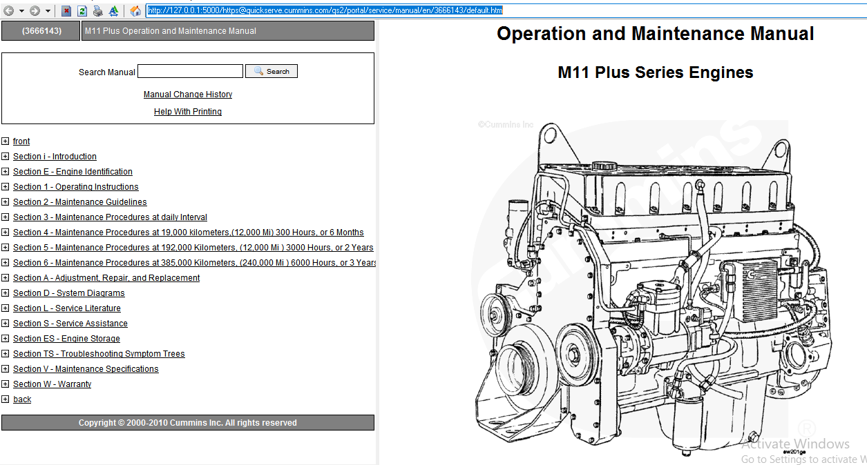
Cummins m11 fuel system diagram. Each of these is described in detail in the paragraphs following. Air in the fuel system 6. CUMMINS PT SYSTEM - Centennial College Community Colleges.
Fuel supply line restriction between the fuel pump and the injectors 5. Cummins Group System Exploded Diagram Section I Remove STC Engines Remove the fuel tubing and AFC air signal line. Factory Cummins service manual for the M11 STC CELECT CELECT Plus engine.
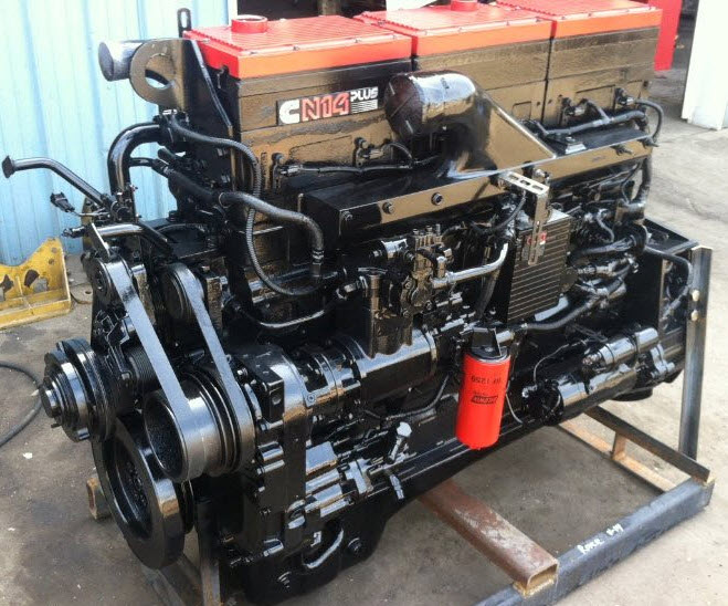
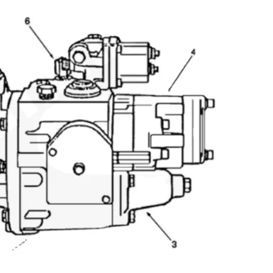
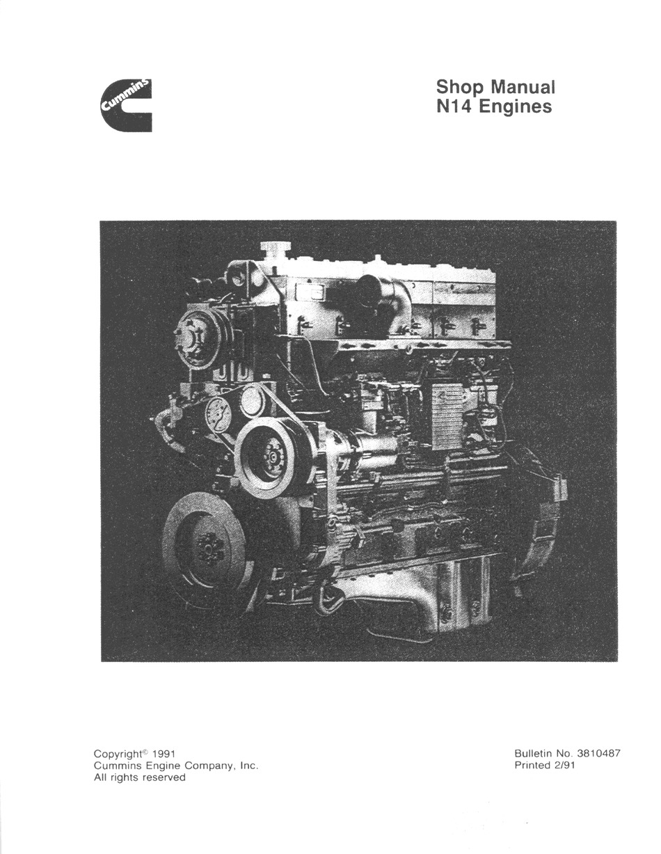
Fuel grade is not correct or fuel quality is poor 4. Cummins N14 Fuel Pump. Use for troubleshooting maintenance repair overhaul.
Fuel System Group 05. Cummins PT Fuel System Parts is mainly used for M11NT855K19K38K50 enginesincluding PT fuel injectorSTC and PTD typePT fuel pumpbarrel and plungerinjector cup and other injector parts such as seal o-ringfilteradapterwasherspringretainertappet valve and. Cummins Engine Company Inc.
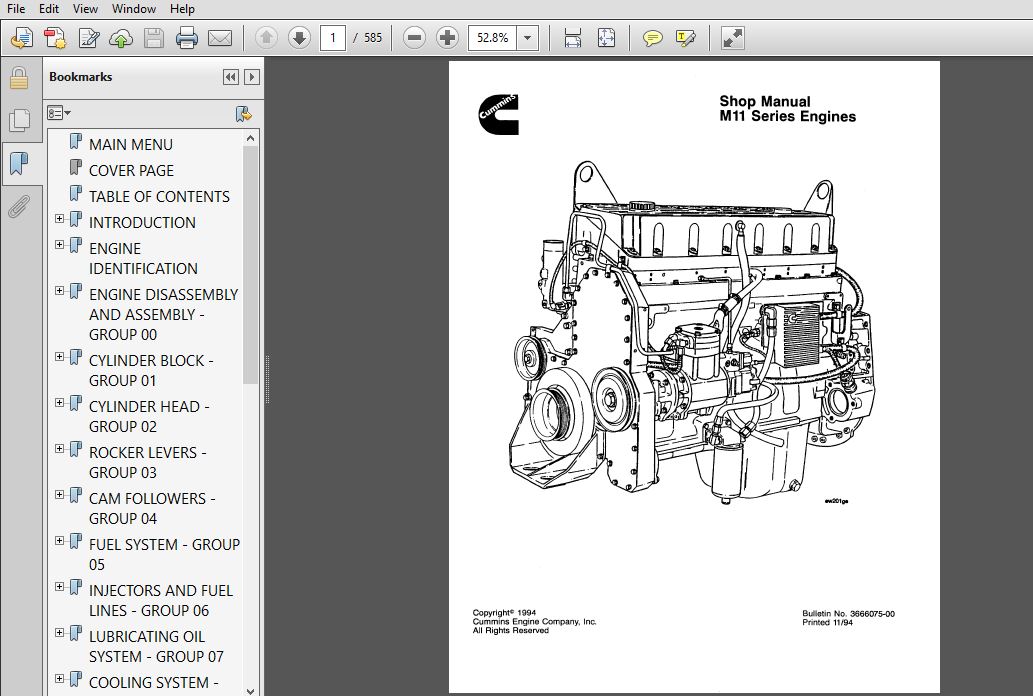
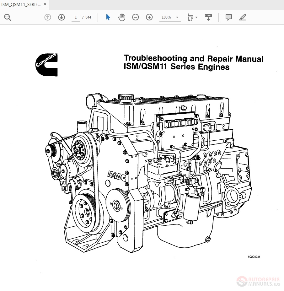
Lubricating Oil System Flow. CUMMINS M11 SERIES ENGINES SERVICE REPAIR MANUAL. Modern diesel engines are complicated and their proper repair requires documentation for even the most skilled technician.
Section i - Introduction M11. Cummins CELECT Injectors provide. From diagrams of the M11 fuel system to troubleshooting instructions for L10 rocker levels Cummins manuals assist staff in completing repairs quickly and keeping the department efficient.
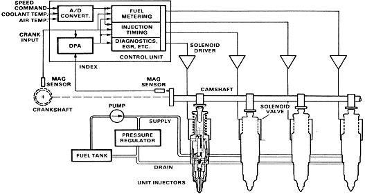
Starter 11 The principle of the PT Fuel System is based on the. HPI-TP Fuel System Heavy Duty High Pressure Injection - Time Pressure Fuel System The fuel system developed for the Signature and ISX CM Fuel System Cummins Ontario Training In these diagrams the Timing.
Cummins Engine Company Inc.
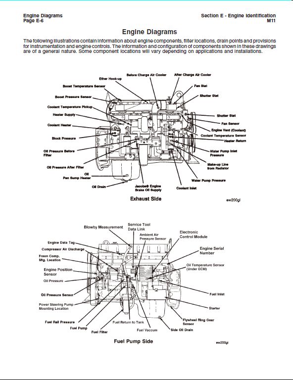
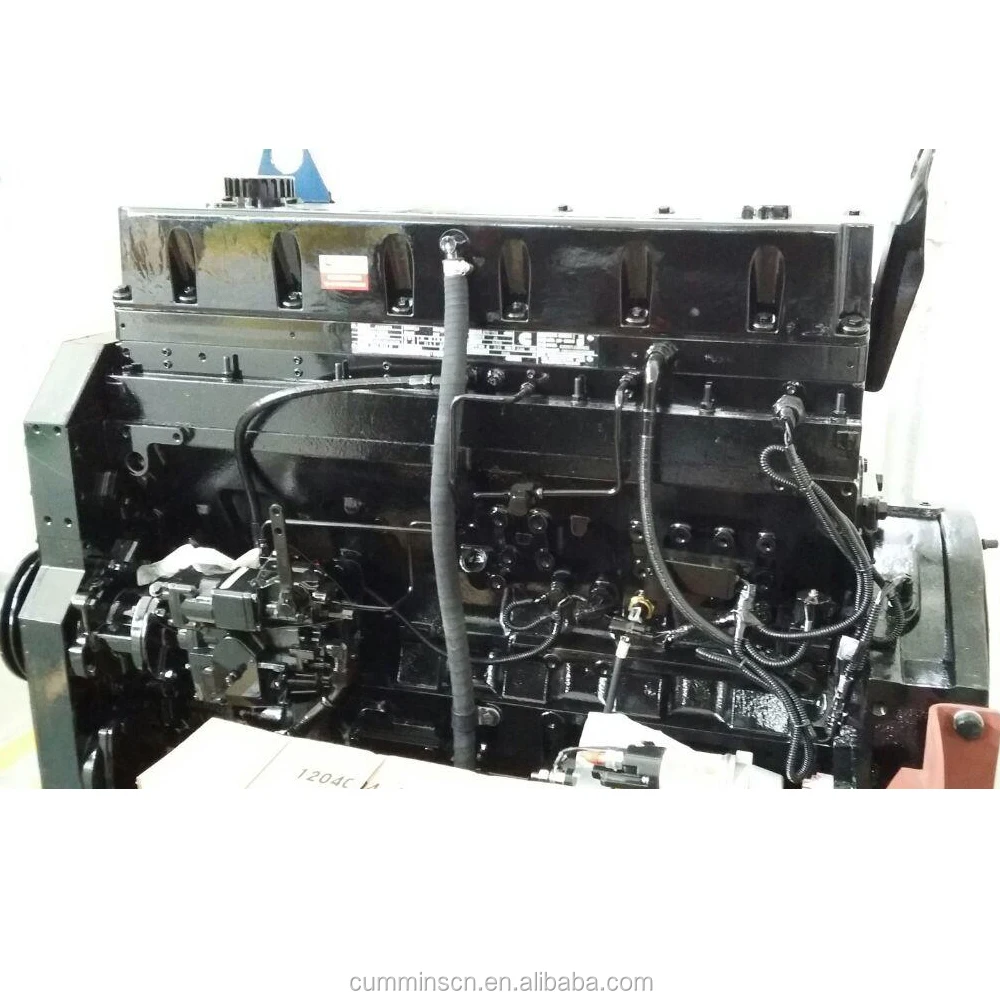
Wiring Diagram 3911868 1 3033800 Washer. If you find differences. The majority of engines used in power generation are the High Horsepower group. Engine Diagrams The following illustrations contain information about engine components. M11 Engine Diagram_exhaust side. Cummins N14 fuel problem Fix - YouTube. PT fuel pump AFC operation is malfunctioning or no air setting on the fuel pump is not set correctly EUGENE 4036 West 1st Ave. The M11-400E Plus M11-370E Plus and M11-350E Plus with 2100 rpm governed speed are ideally suited for vocational applications. Gear pumpCummins N14 Fuel Pump Diagrams from n14 cummins fuel system diagram.
PT fuel pump AFC operation is malfunctioning or no air setting on the fuel pump is not set correctly EUGENE 4036 West 1st Ave. Cummins ISBe QSB Engine Service Manual w Common Rail Fuel System 285. Lubricating Oil System Flow. M11 Engine Diagram_fuel pump side. The majority of engines used in power generation are the High Horsepower group. Modern diesel engines are complicated and their proper repair requires documentation for even the most skilled technician. Gear pumpCummins N14 Fuel Pump Diagrams from n14 cummins fuel system diagram.















Post a Comment for "Cummins M11 Fuel System Diagram"